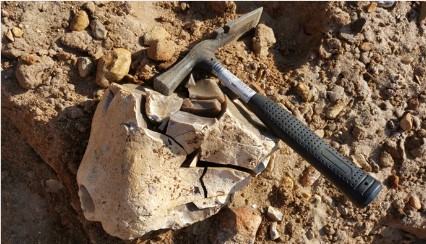
On-site material sampling of representative samples, accompanied by a local geologist.
On-site material sampling of representative samples, accompanied by a local geologist.
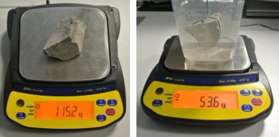
Estimation of material density according to ISO 1183-1 by immersing the selected samples in water.
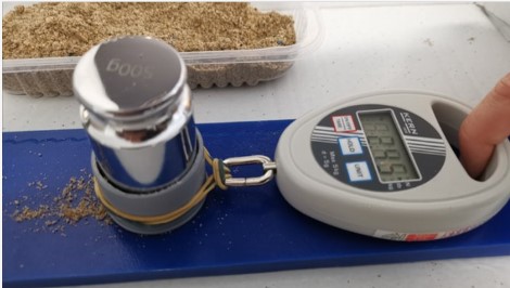
Execution of Express Wall Friction Test (EWFT) with a mobile device on-site, measuring the angle and coefficient of static wall friction, as well as the adhesion of static friction.
Execution of Point Load Test (PLT) with a mobile PLT device on-site, applying strength, deformation, and crushing energy measurements.
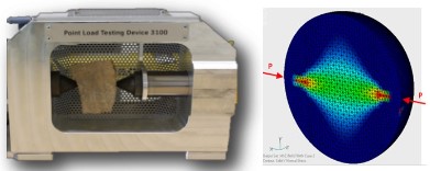
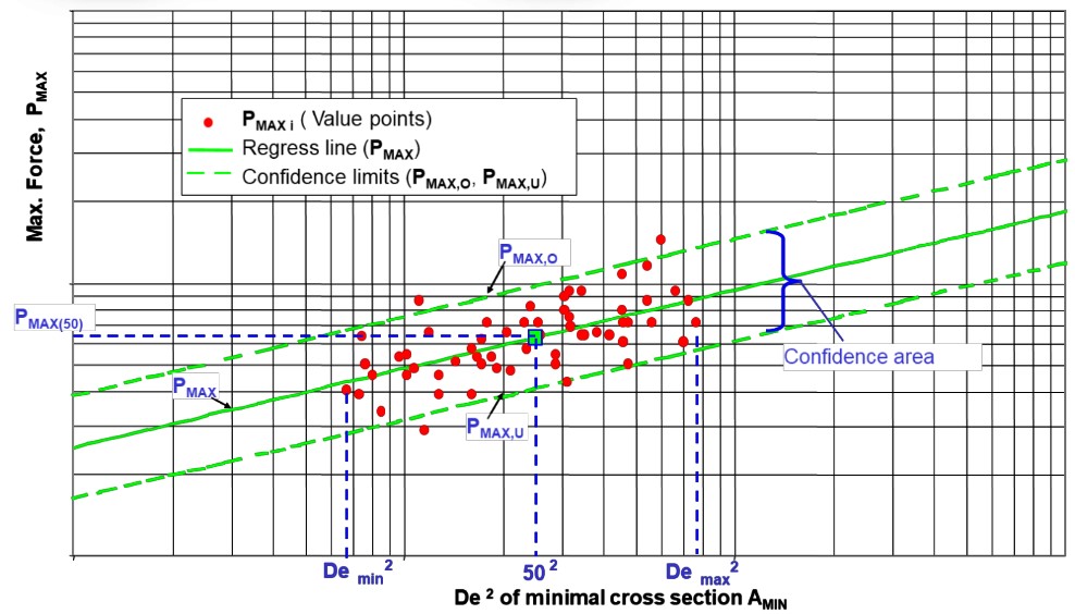
Evaluation of strength values: PLT failure force (Pmax(50)) or PLT index (Is(50)), with estimation of compressive strength (UCS); inclination of the regression line in the 'sample size-failure force' diagram and estimation of weathering degree; width of the confidence area (strength deviation).
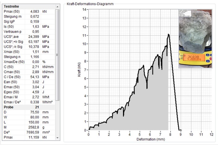
Evaluation of sample deformation by applying point load force, with estimation of crushing energy based on sample failure.
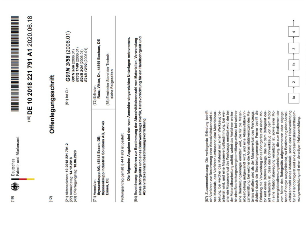
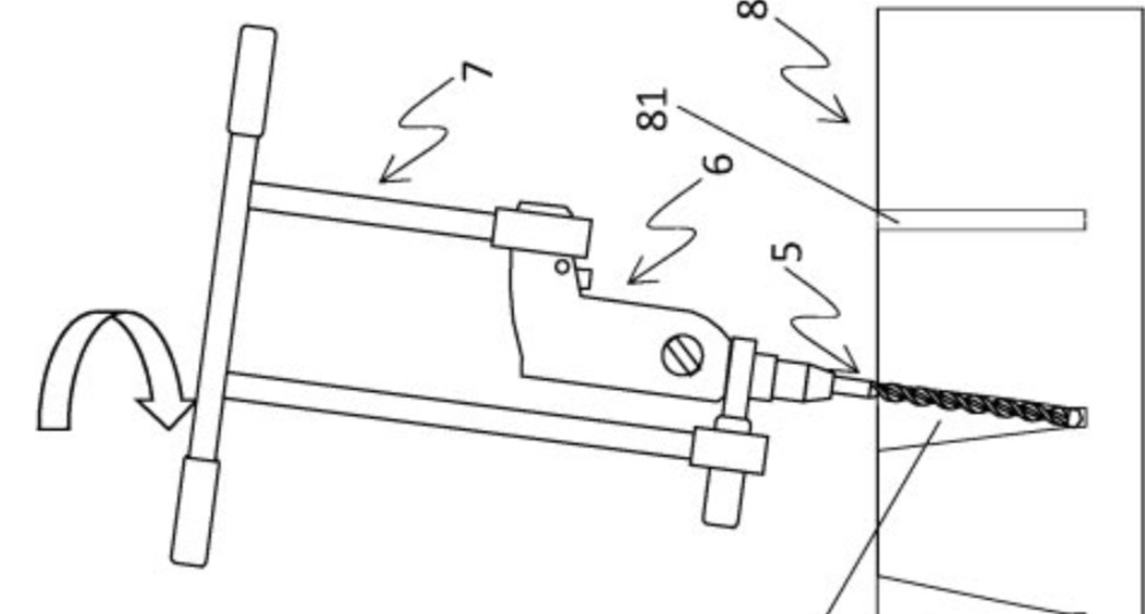
Execution of Express Drill Abrasiveness Tests (EDAT) with a mobile EDAT device on-site, measuring energy consumption during drilling and wear of drill bits, according to the disclosure document No. DE102018221791A1.
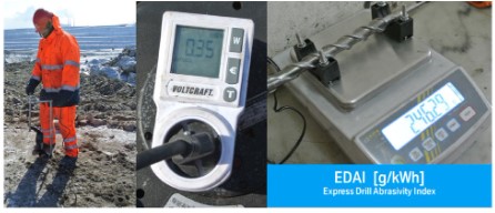
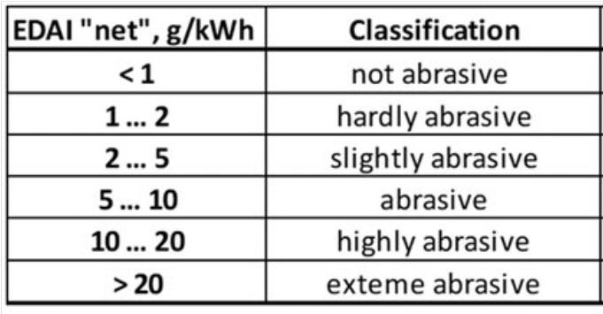
Evaluation of EDAT measurements and estimation of the Express Drill Abrasiveness Index (EDAI) and Required Drill Energy (RDE).
Comparison with the existing EDAI database, classification of abrasiveness, and estimation of key abrasiveness figures, including the Bond Abrasion Index (Ai) and Cerchar Abrasiveness Index (CAI).
Selection of the most suitable mining and primary crushing equipment (BWE, DRC, or Sizer) for the specific application in the investigated mine, based on measured material properties.

Design and optimization of cutting and crushing tools for both new and existing mining equipment, based on material properties, Lump Size Distribution (LSD) of feed, production rate, and maximal product size.
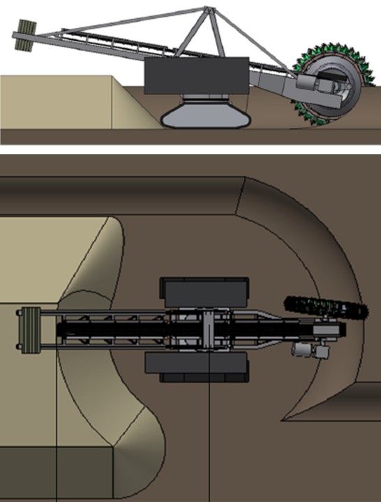
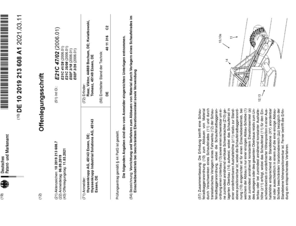
Mining of minerals in an open-pit mine in a single-slice operation with the help of a bucket-wheel excavator, creating a stockpile, according to the disclosure document No. DE102019213608A1.
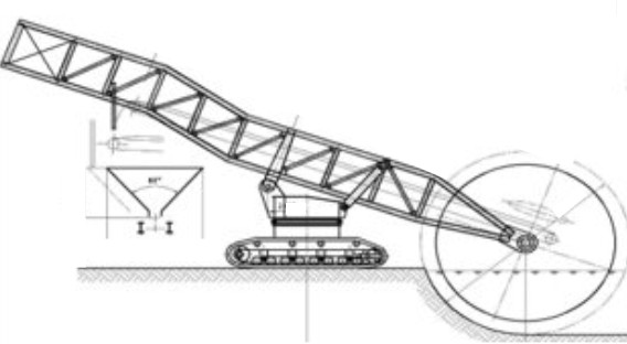
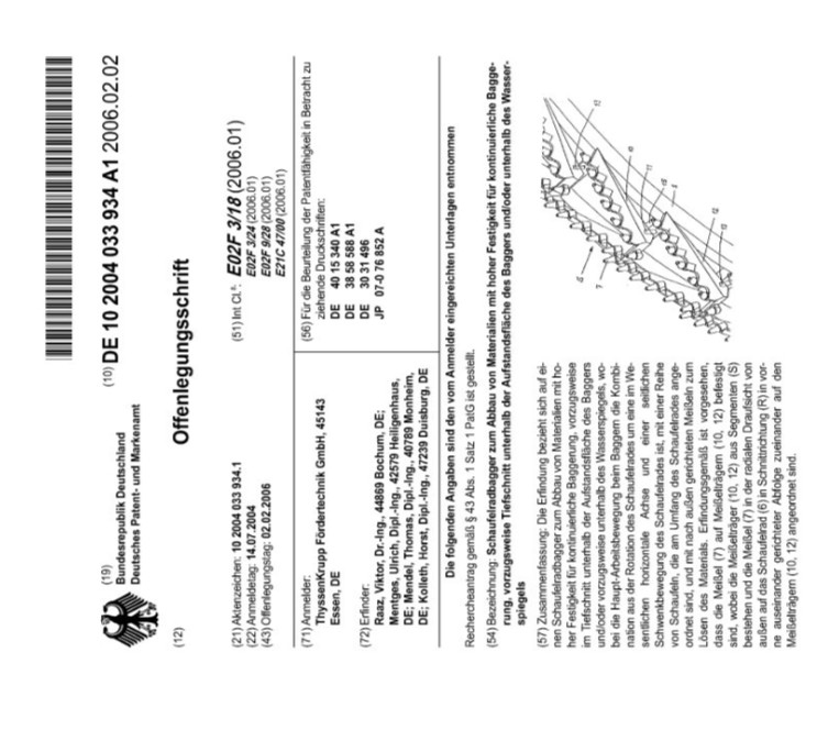
Mining of hard minerals in an open-pit mine below the stand level with the help of a bucket-wheel excavator, according to the disclosure document No. DE102004033934A1.
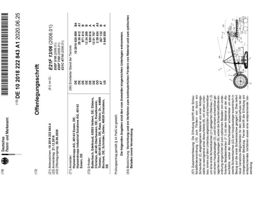
Mining of minerals in an open-pit mine with the help of a bucket-wheel excavator, loading mining trucks without interruption, according to the disclosure document No. DE10201822843A1.
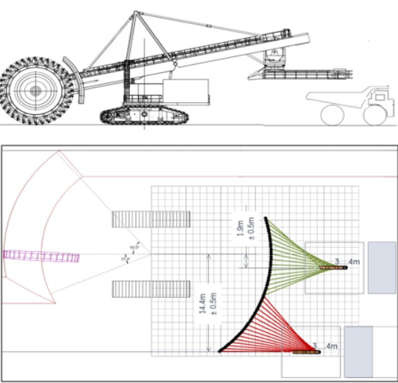
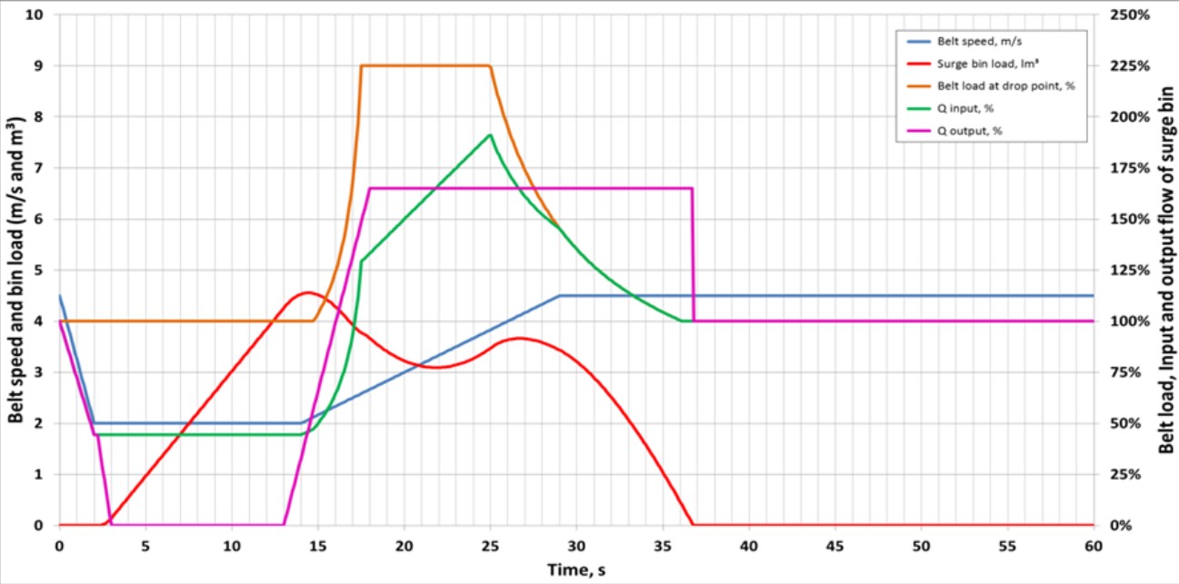
Capture of specific block geometry and operational methods for existing or planned mining operations for a specific BWE.

Simulation of existing mining methods in a block efficiency calculation program for BWE, and validation of the maximum possible production efficiency.

Optimization of mining block geometry and operational parameters to increase the mining efficiency of BWE.
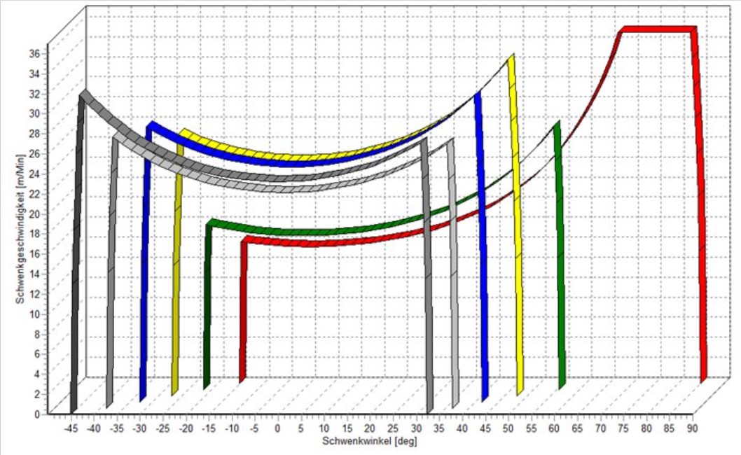
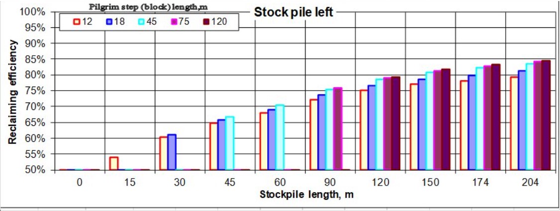
Simulation of existing or proposed mining methods in a pile efficiency calculation program for BWR, and validation of the maximum possible production efficiency.
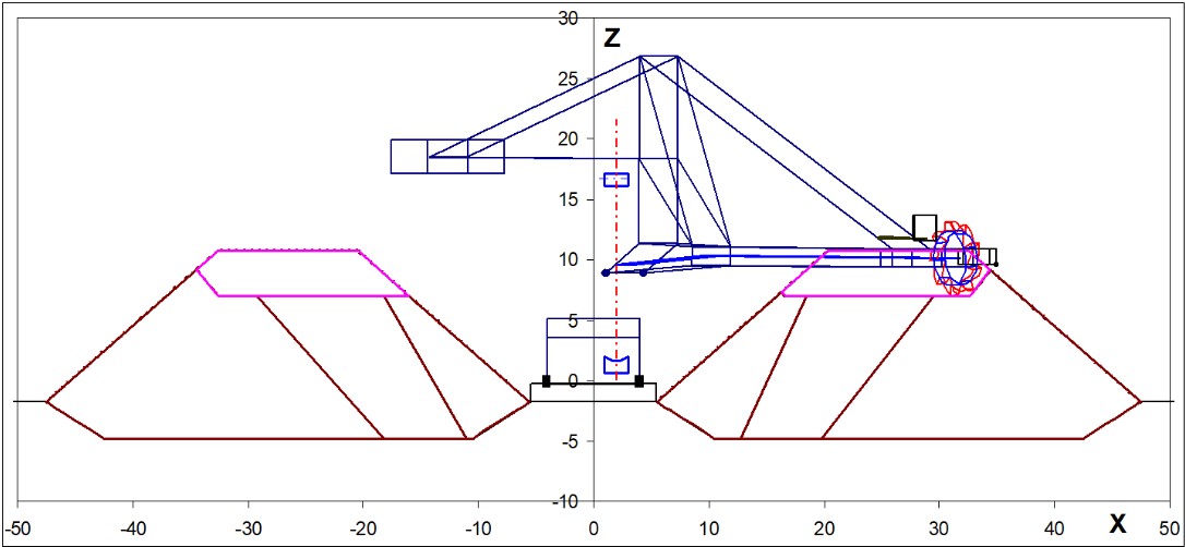
Optimization of reclaiming operational parameters for each mining method to increase the reclaiming efficiency of BWR.
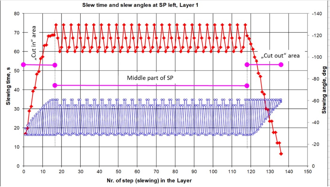
Comparison of different BWR reclaiming methods to select the most efficient one.
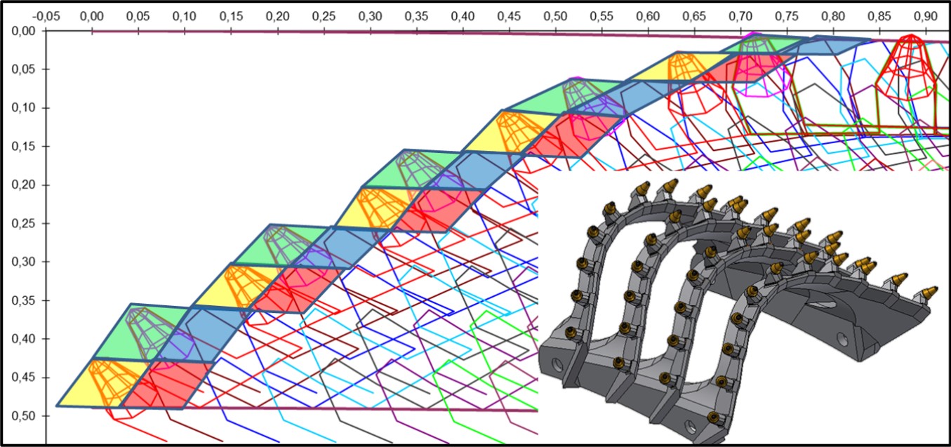
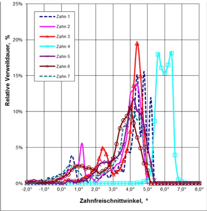
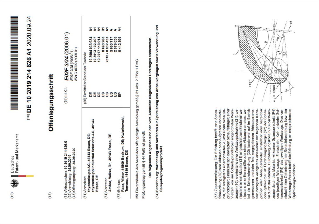
Cut simulation of existing or new buckets of a BWE or BWR in a mining block for each possible position, with quantitative evaluation of cut cross-sections, free cut angles, and side setting angles for each tooth on the bucket, according to the disclosure document No. DE102019214626A1.
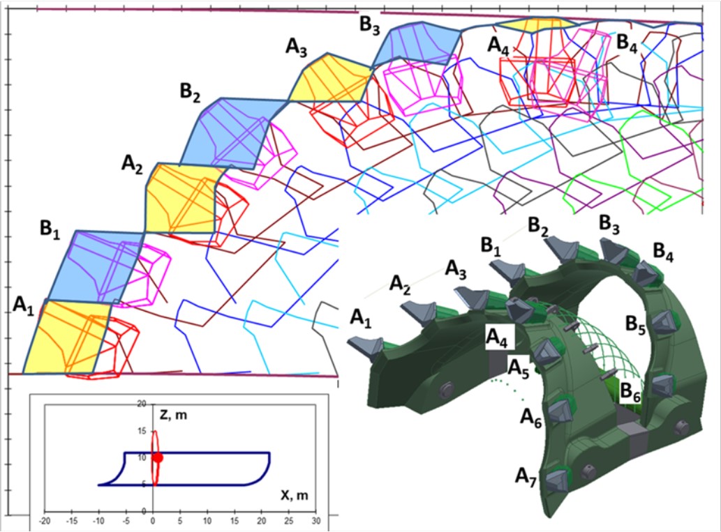
Statistical evaluation of the residence probability for each tooth row with different cut cross-sections, side settings, and free cut angles.
Optimization of the bucket and tooth shape, arrangement, and angle orientation to reduce cutting force, as well as tooth and bucket wear, based on simulation results.
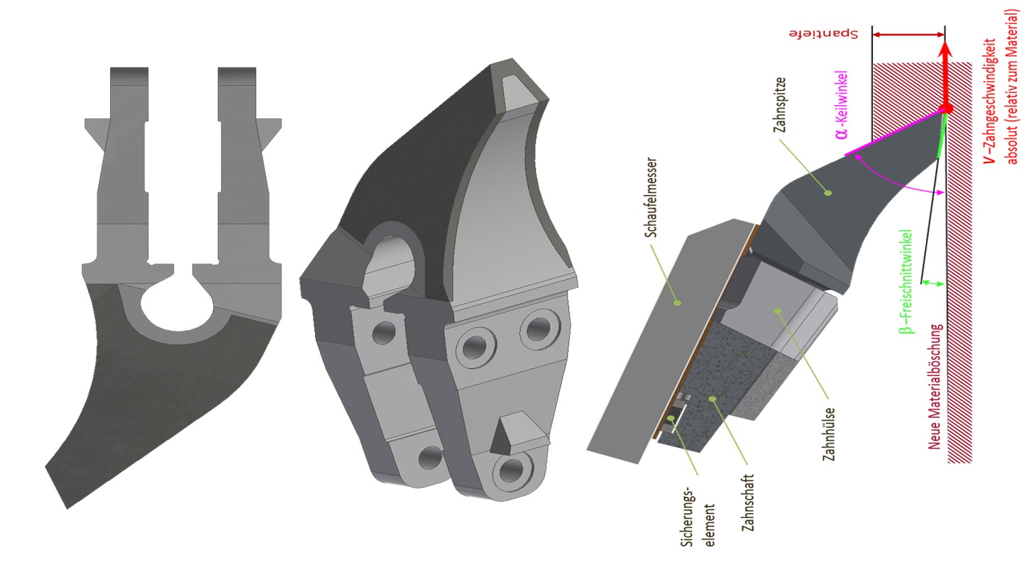
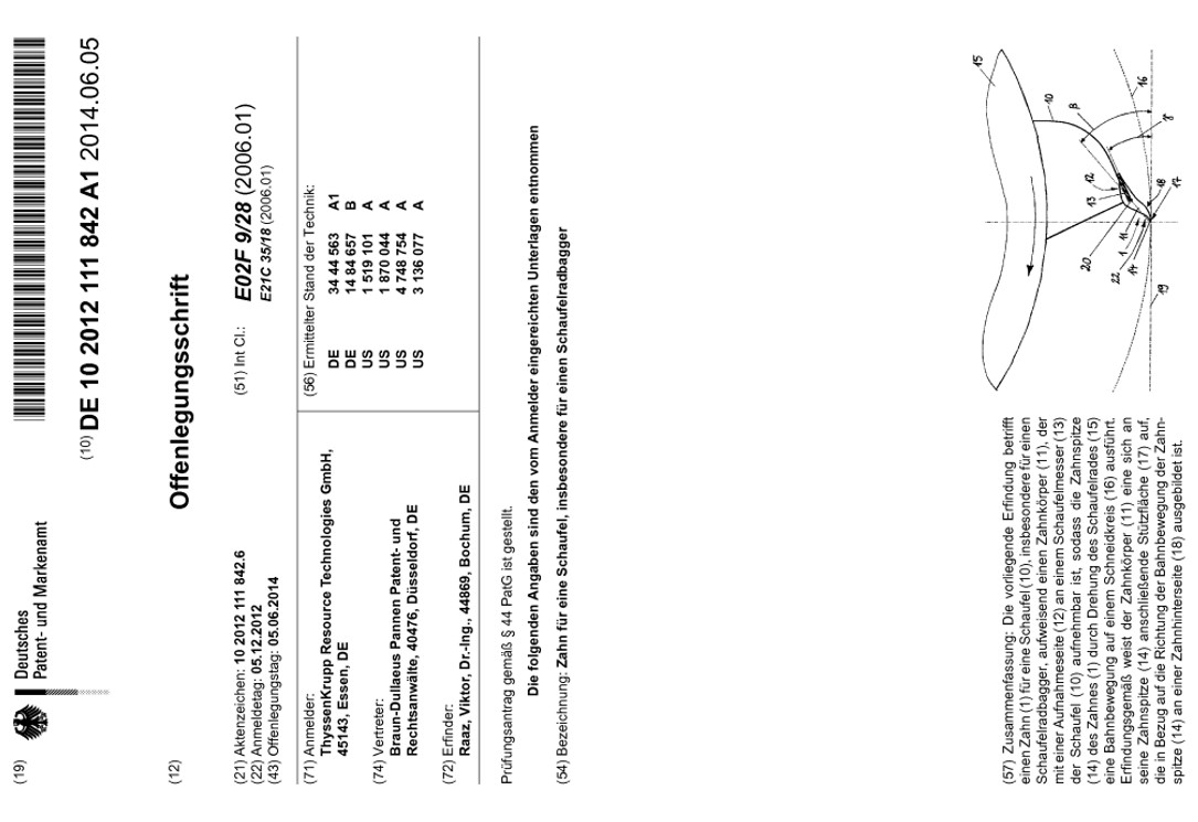
Tooth design for bucket-wheel excavators for the extraction of materials with very high strength, according to the disclosure document No. DE102012111842A1.
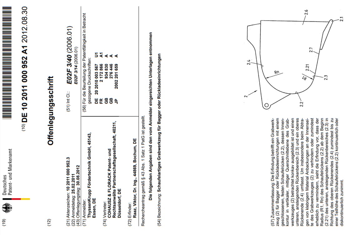
Rear wall design of excavator and backhoe buckets to reduce the adhesion of sticky materials in the bucket, according to the disclosure document No. DE102011000952A1.
Prediction of abrasive wear for cutting and crushing tools based on material abrasiveness (e.g., EDAI, BOND abrasiveness, CAI, LCPC), energy consumption for comminution (using PLT or EDAT energy consumption data), and wear resistance factors of the tool materials.
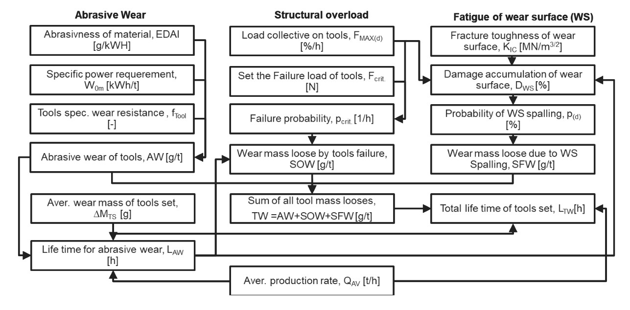
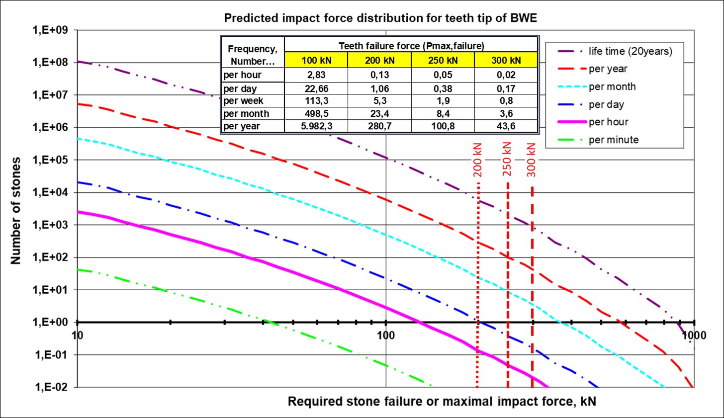
Statistical calculation of the probability of exceeding the maximum design load for cutting tools to predict structural overload, based on PLT investigations and LSD of hard stones in the feed.
Evaluation of lump size distribution for large lumps in the feed based on images captured by cameras over the transport belt.

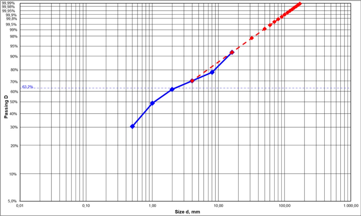
Prediction of the probability of large stones in the larger size range based on the sieve curve.
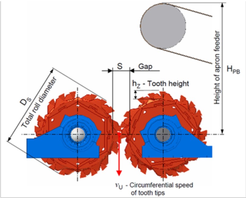
Calculation of throughput rate, output LSD, required drive power, and crushing force distribution on the teeth based on PLT results, roll dimensions, gap, tooth height, and roll speed.
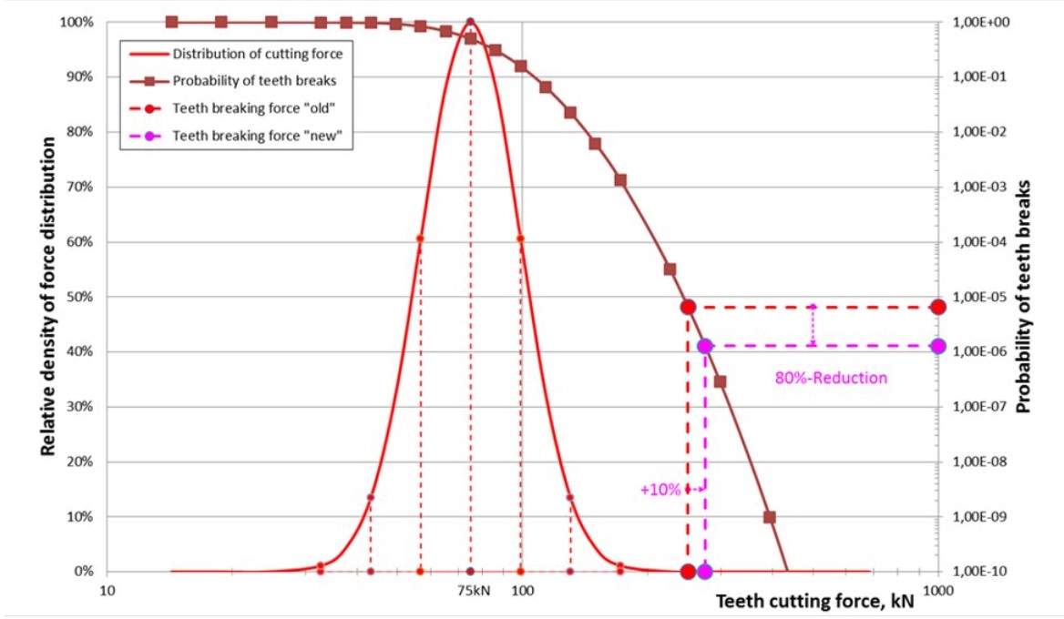
Prediction of impact and crushing load distribution on the crushing teeth of rolls, probability of tooth breakage, and processing time for large lumps.
Dynamic simulation of starting, stalling, and crushing of hard stones using different drive configurations, aiming to select the most suitable drive or its setting parameters based on material properties of feed (strength and size of hard stones).
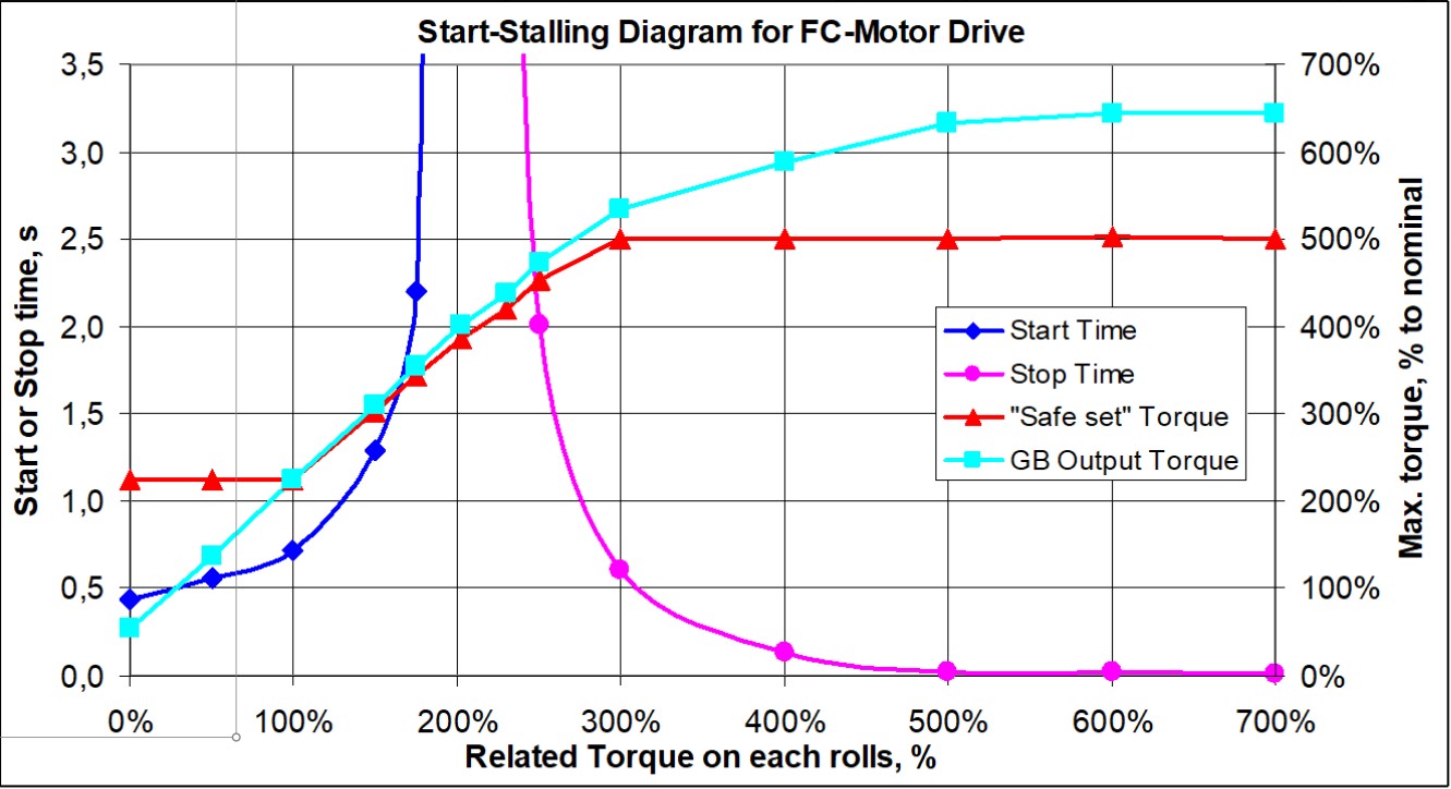
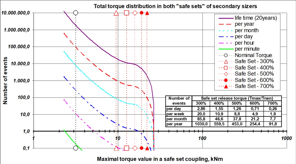
Prediction of the probability of release for safety couplings in a selected drive configuration for specific applications of DRC or sizers, based on dynamic simulations that consider the composition of the feed material, including known percentages, LSD and the strength of the hard lumps.
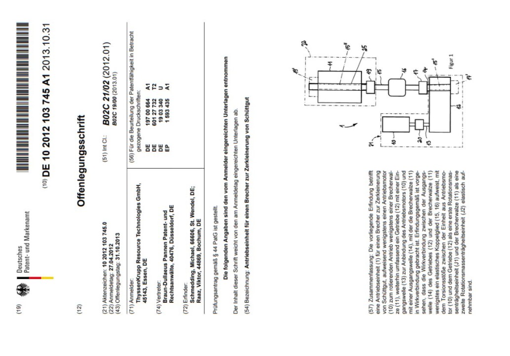
Design of sizer drives with long torsional shafts between the gearbox and crushing rolls to reduce the high dynamic peaks of torque in the drive, according to disclosure document No. DE102012103745A1.
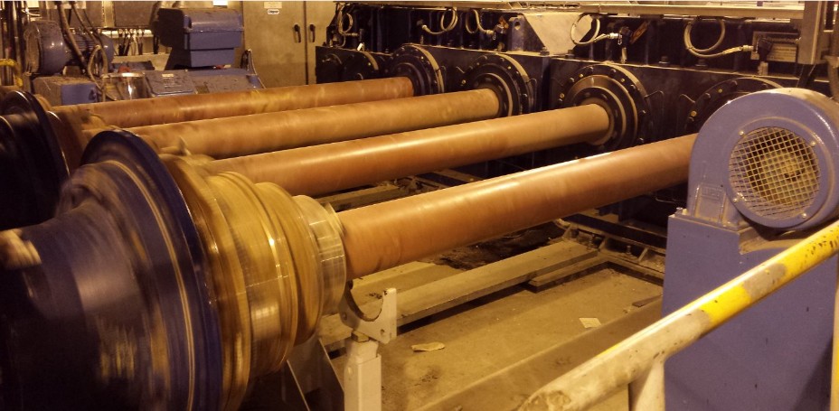
Optimization of setting parameters for existing DRC or sizer drives to increase crusher availability by frequent release of their safety couplings.
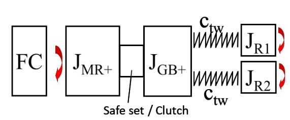
Rotational vibration analysis for crusher and bucket wheel drives with determination of natural frequencies, torsional vibration modes and critical speeds.


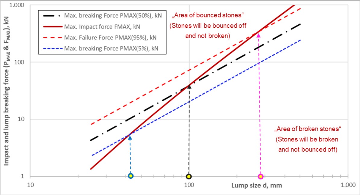
Prediction of the maximal force during the impact of stones with BWE teeth while cutting material, based on the knowledge of the impact force progression from TU BAF/Germany.
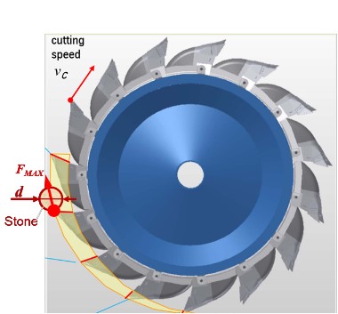
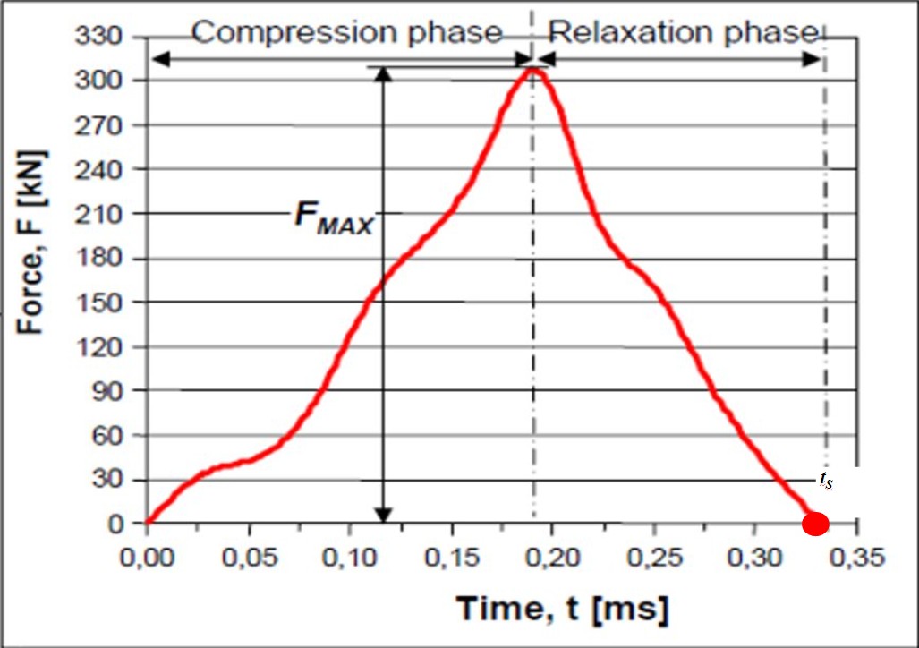
The percentage of bouncing or crushing of impacted stones depends on cutting speed, stone size, and material strength (PLT results).
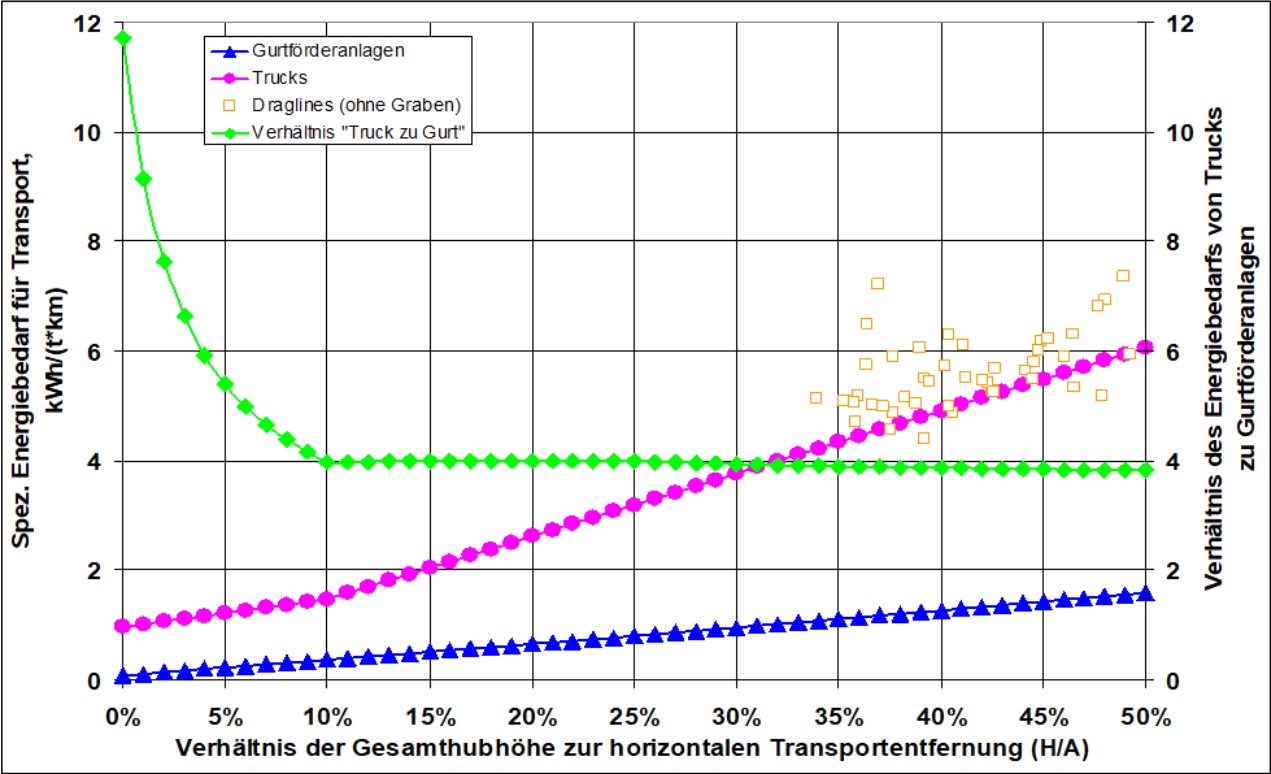
Calculation of the energy efficiency and CO2 emissions of various open pit mining technologies according to the TKF method (WorldCoal, Nov. 2009)
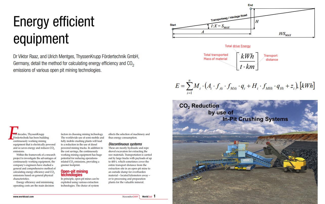
Comparison of energy consumption for trucks, belt conveyors, and draglines relative to the mass of hauled material and the shortest horizontal transportation distance.
Life-cycle monitoring of energy efficiency for an operational material handling and/or mining system: main requirements, common KPIs, calculation methods, accuracy, and user interface design.

Energy and CO₂ tracking for mining and processing equipment based on KPIs. Preparation and distribution of various KPI information to different user groups.
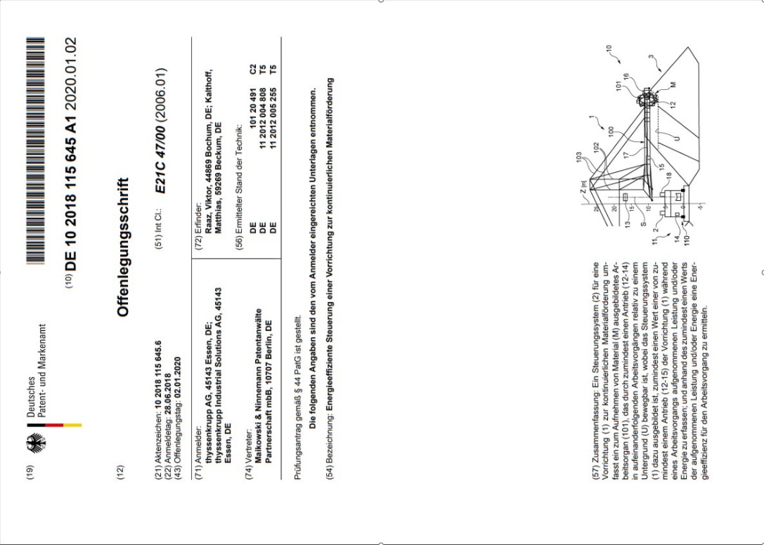
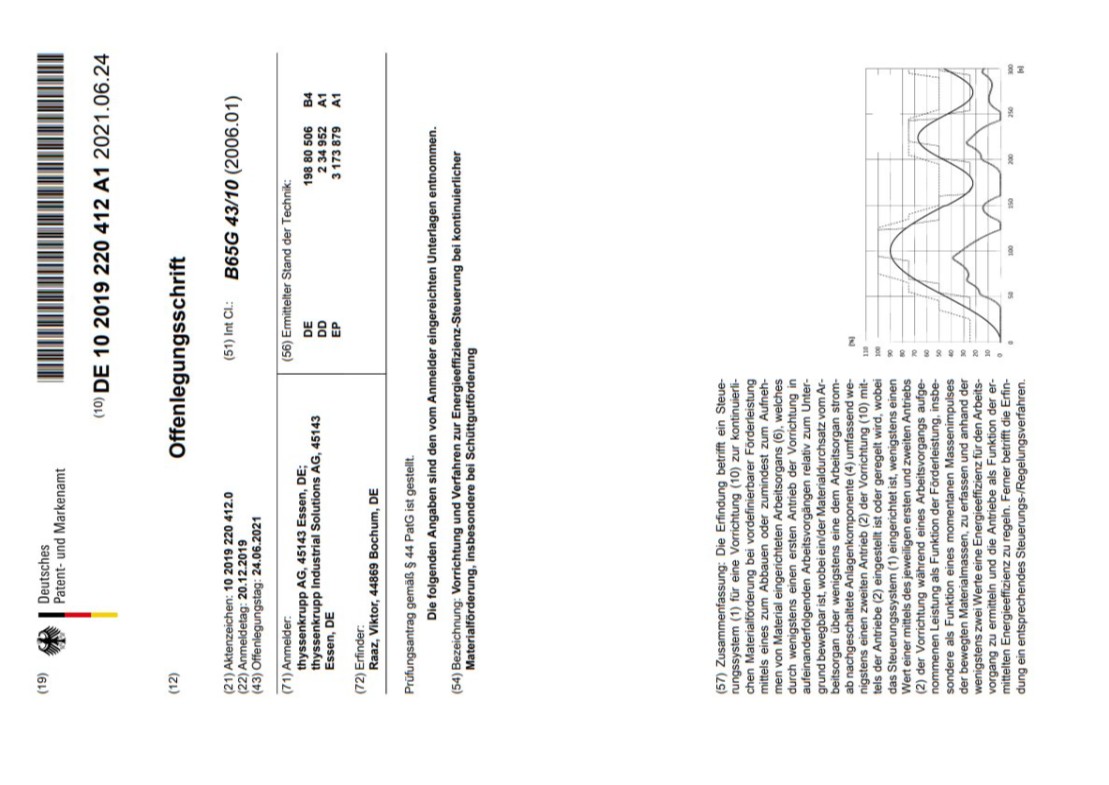
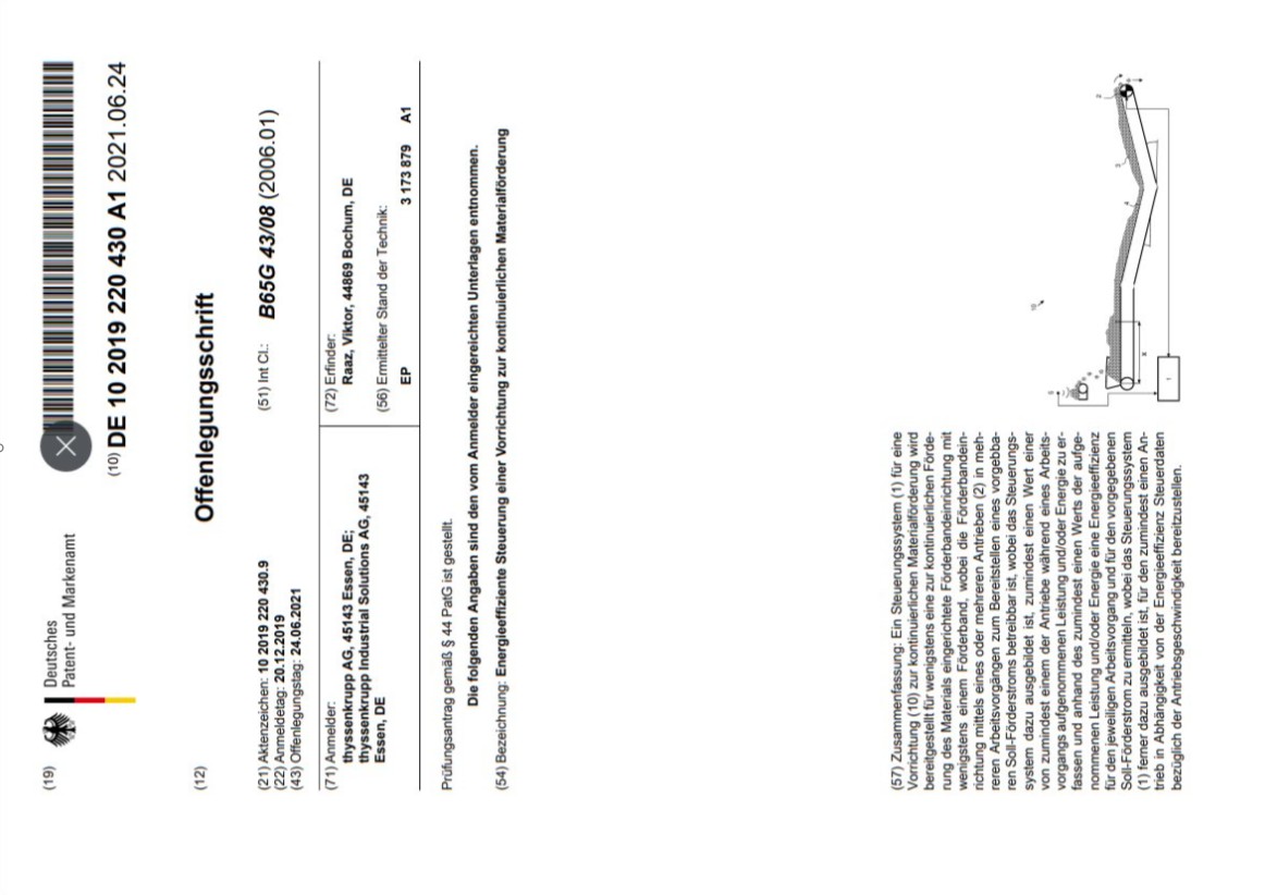
Implementation of an energy-saving control algorithm in control systems for mining and transport equipment according to the disclosure documents No. DE102018115645A1, DE102019220412A1, DE102019220430A1.
Life evaluation of drive power for an empty belt and the total running resistance factor during belt operation under varying load conditions.
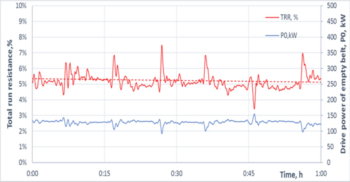
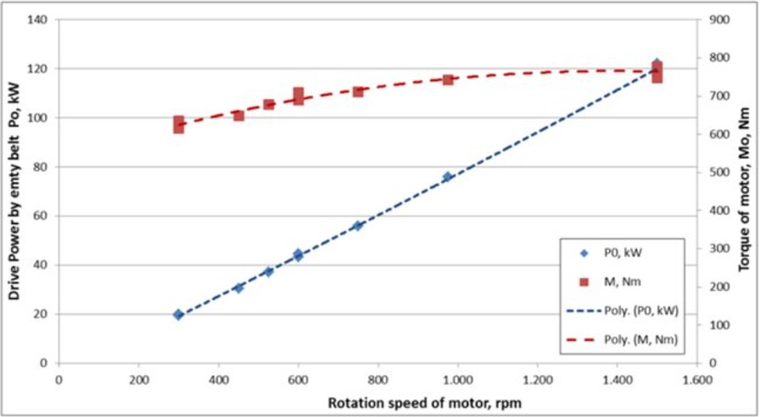
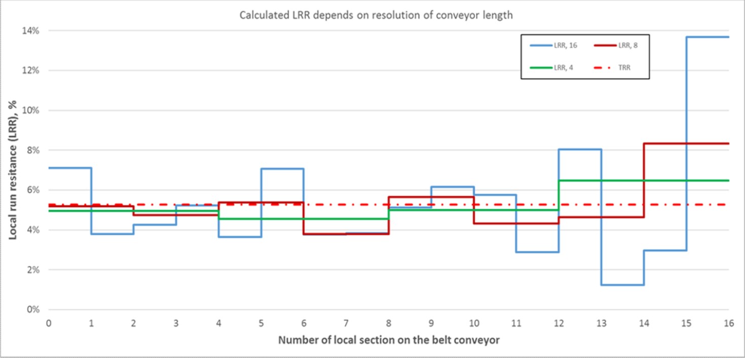
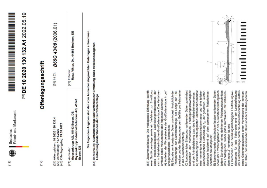
Calculation of local running resistance for different sections of belt conveyors based on measurements of total drive power and throughput rate, according to the disclosure document No. DE102020130132A1.
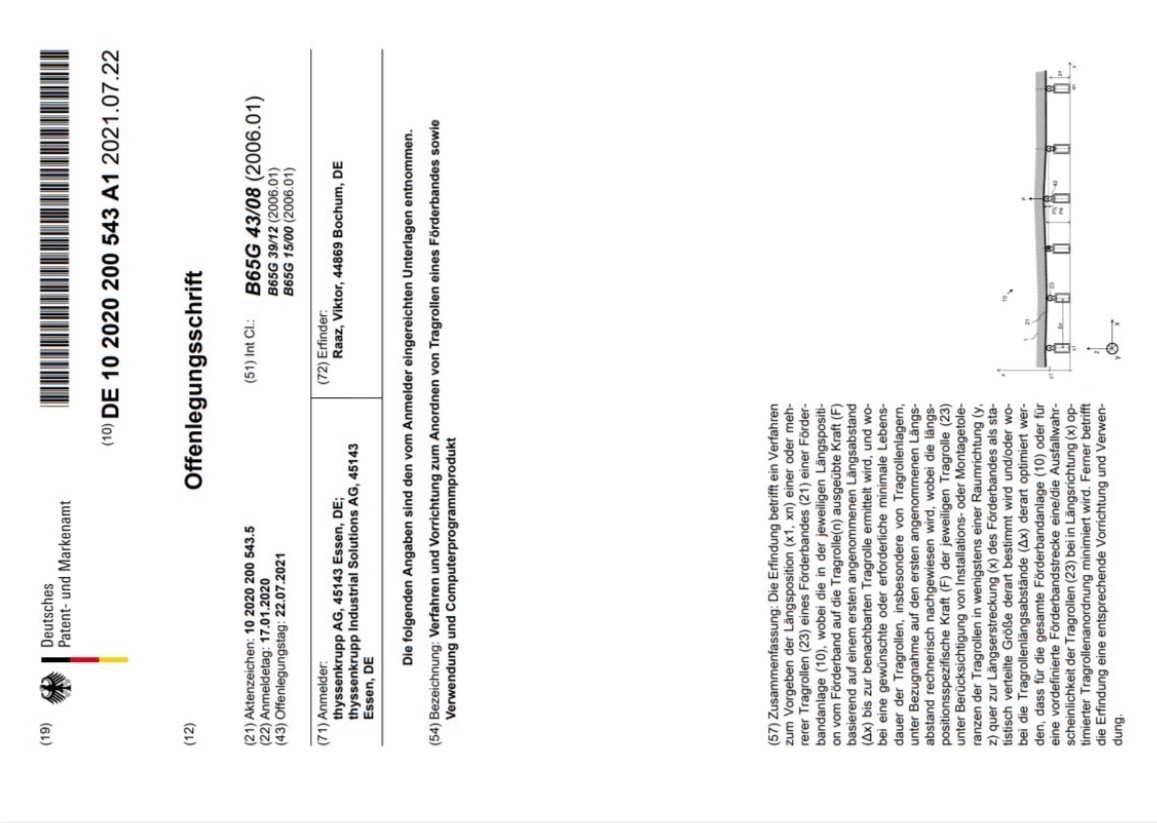
Extension of the existing calculation method for the lifetime assessment of the idlers in a belt conveyor system by considering assembly-induced deviations of the idler station coordinates from the 'ideal' planned line according to the disclosure document No. DE102020200543A1.

Consideration of the transverse bending stiffness of the troughed or rolled conveyor belt under local belt tension and rubber deflection, through the calculation of the force distribution between adjacent idler stations.
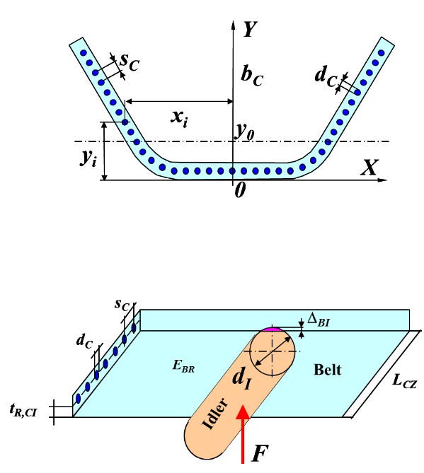
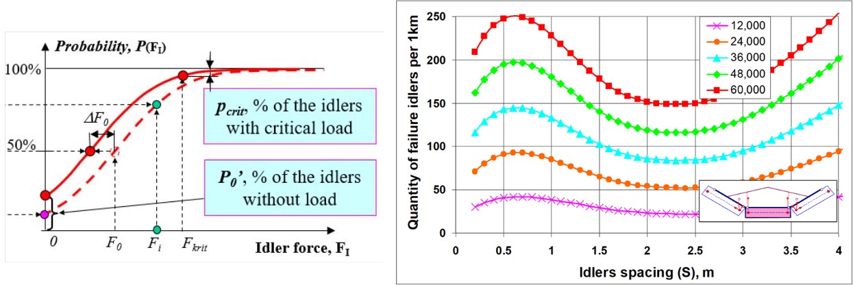
Statistical calculation of the expected percentage of idlers without load and idlers with critical loads due to installation inaccuracies, in order to account for this in the force distribution and lifetime calculation.
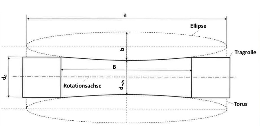
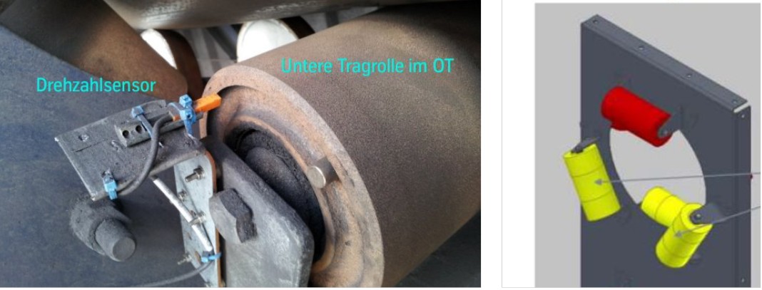
Expertise in the design of toroidal idlers and the selection of the optimal degree of idler slimming for a specific belt conveyor application to achieve the maximum reduction in running resistance according to WO 2020/249531 A1.
Preparation and execution of rotational speed measurements on the idlers of the existing belt conveyor to select the optimal shape of toroidal idlers, as well as the evaluation of the expected reductions in drive power, energy consumption, and CO2 emissions.
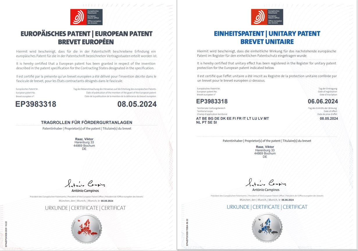
Licensing for the use of the patents EP3983318, CN113993797B, US11661284B2, AU2020292572B2 for the manufacturing of toroidal idlers by the preferred idler manufacturer.
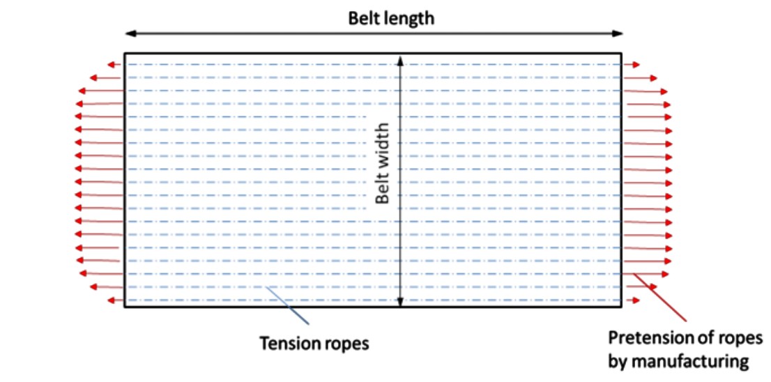
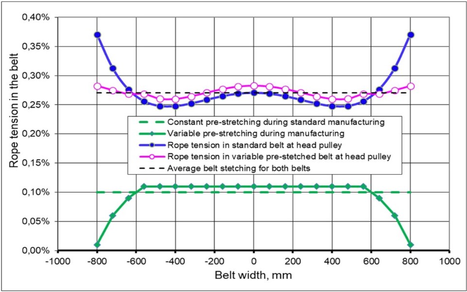
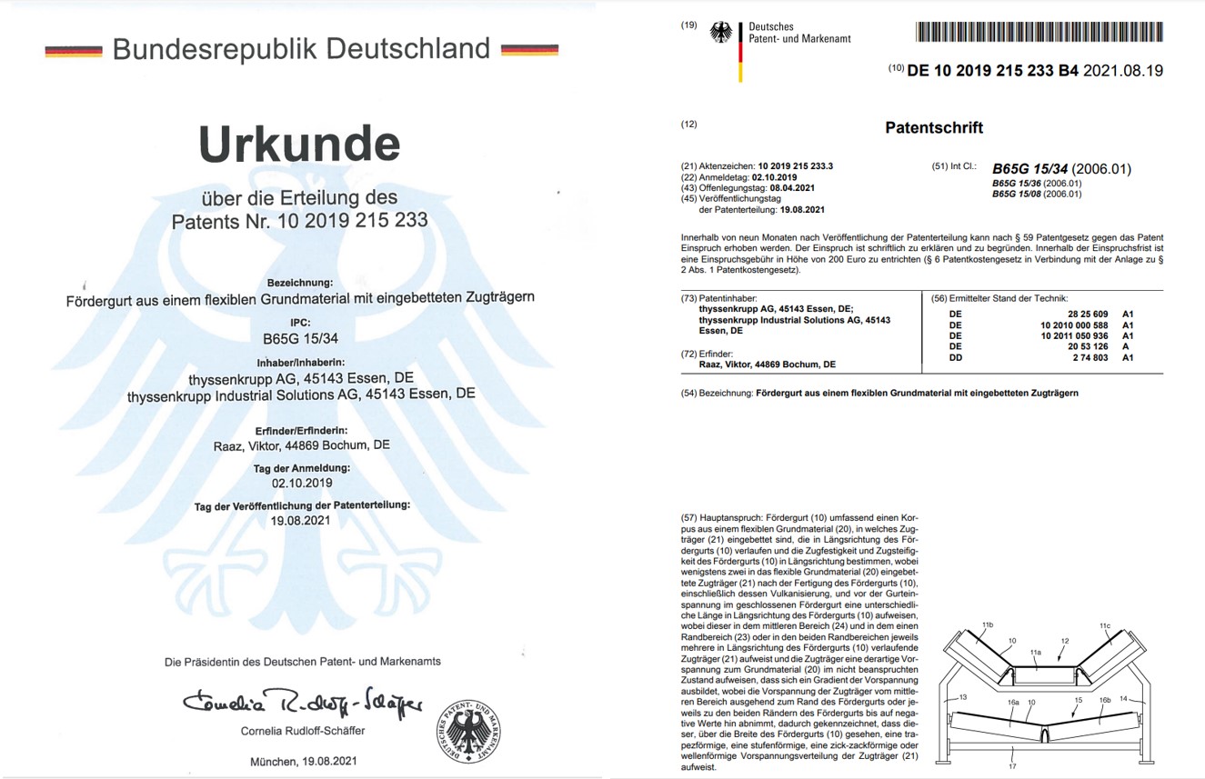
Selection of the suitable load pretension distribution, that during the manufacturing of the belt is to apply to the ropes, in order to have the different ropes length and the best equalization of the rope tension during the operation with maximal load.
Simulation of rope strength during the operation of belt conveyor under different load conditions. Evaluation of possible reduction for belt strength class for the specific application and commercial impact.
Licensing for the use of the patent DE102019215233 for manufacturing of the belt with different pretension (etc. rope length).
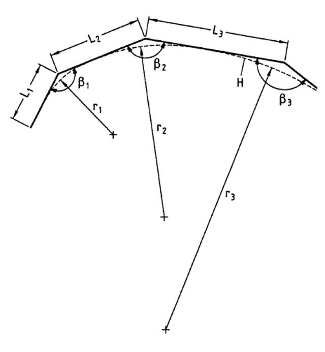
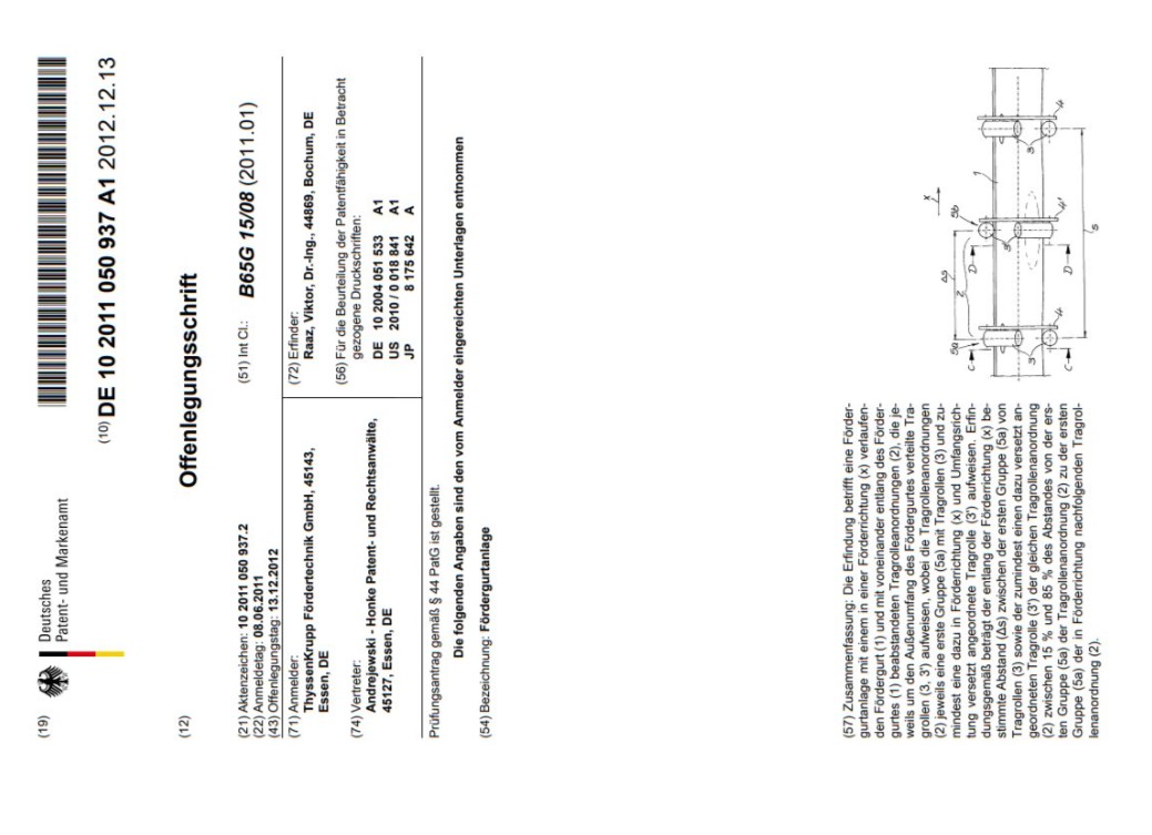
Offsetting of the central and side support rollers of a conveyor belt system in the longitudinal direction for the purpose of reducing running resistance and increasing the service life of the conveyor belts according to the disclosure document No. DE102011050937A1.

Simulation of the impact of support roller offset on the support forces of the rollers as well as on the reduction of running resistance, with recommendations for the roller spacing for troughed and rolled conveyor belts.
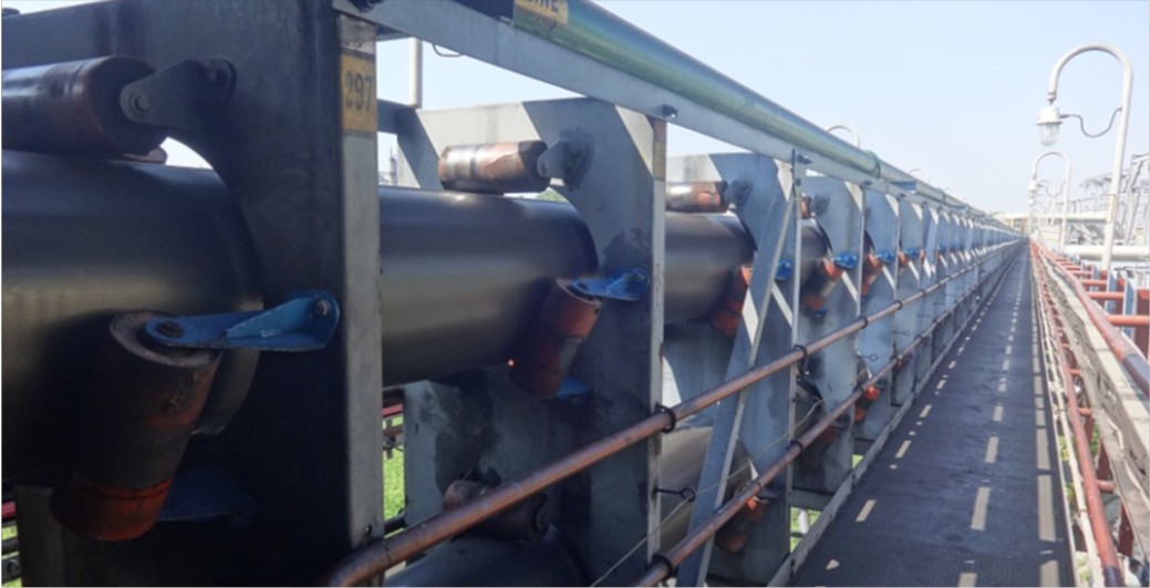
Constructive implementation and economic impact of the modernization of support roller brackets for existing and new conveyor belt systems.
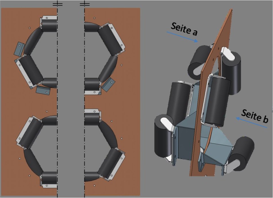
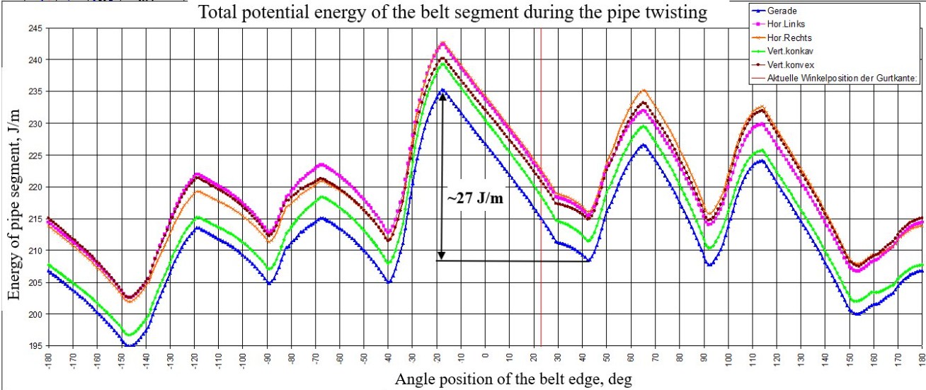
Innovative arrangement of the support rollers of a pipe conveyor at the circumference of pipe for running stability to prevent belt twisting during operation according to the disclosure document No.DE102011052697A1.
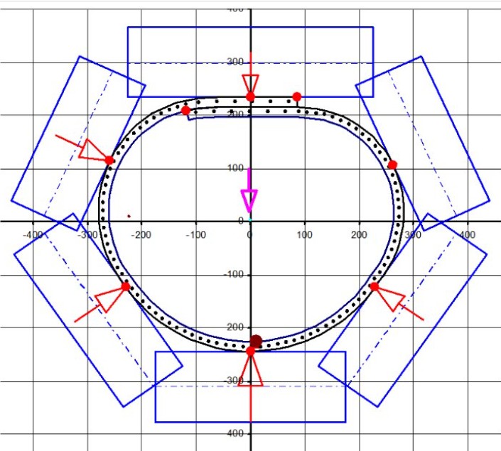
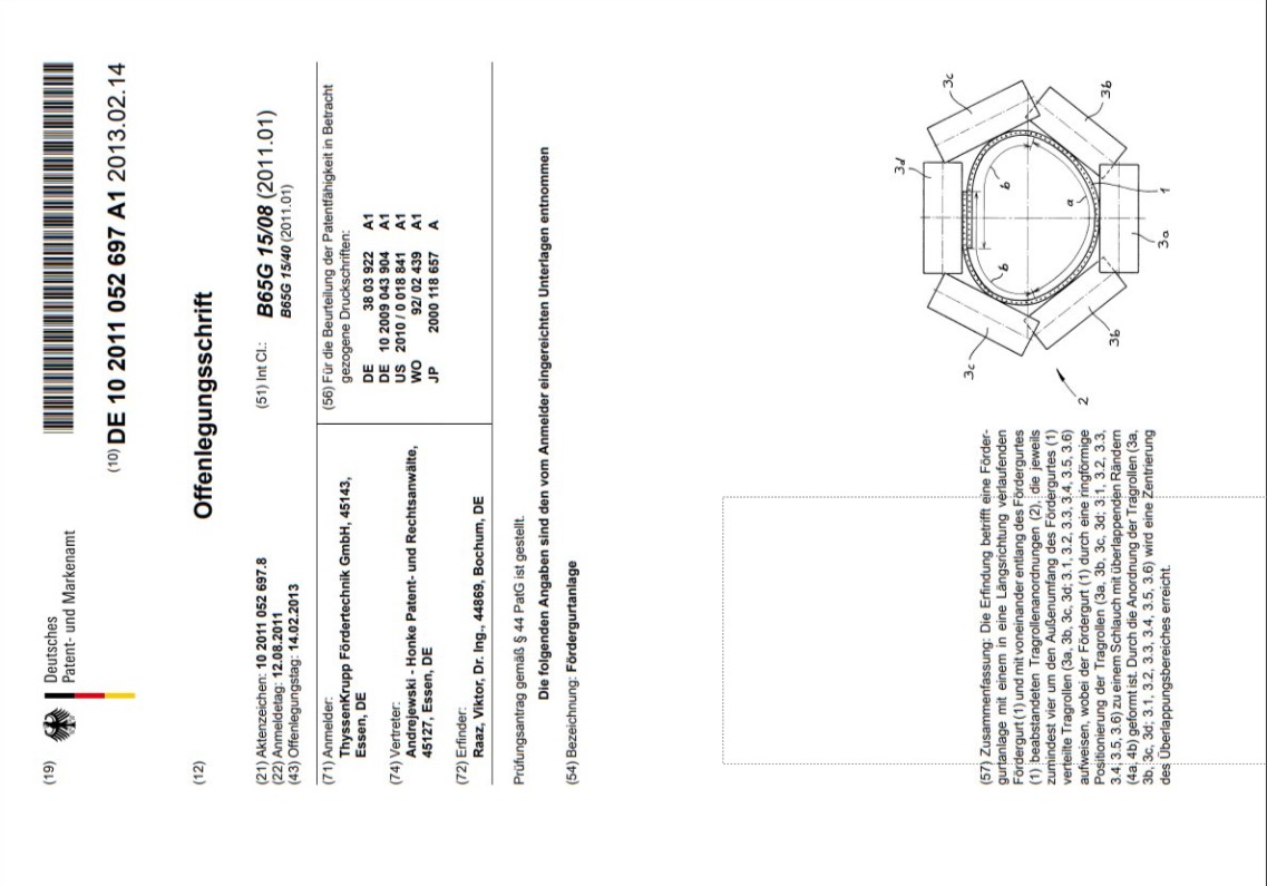
Simulation of the impact of the arrangement of support rollers on the support forces of the rollers as well as on the total potential energy of the belt segment during belt twisting and quantitative estimation of its running stability.
